Uniquely skilled? It's patently obvious!
Published 07.21.2021
News
Student News
Automated Manufacturing & Machining
Engineering Technologies
Culminating a yearlong process, nine manufacturing engineering technology students completed impressive senior projects that reciprocate, rotate, automatically retract, measure force, automatically become buoyant, dispense and measure line cord, efficiently exhaust gases, and mold candies.
“How many people do you know who can make – or specify how to manufacture – just about anything?” asked John M. Good, instructor of automation and computer integrated manufacturing, in introducing the projects prior to the students’ capstone presentations. “These nine manufacturing engineering technology students are uniquely skilled.”
The projects were initiated in the fall, during the Senior Seminar Lecture course, which teaches the theory and practice of defining, planning and cost-estimating engineering problems and includes a formal capstone project proposal. The projects, Good explained, evolved from students’ own ideas, were requested by someone or were simply a form of research and experimentation to determine whether something could be done.
This spring, during the Senior Seminar Lab, the students completed and delivered the projects, each working under a faculty mentor.
“In most cases, the projects are a complex mechanism demonstrating many disciplines,” Good added.
“At least four of these projects may qualify for patents, and at least two are already protected by patent pending status,” he said.
A few of the senior projects:
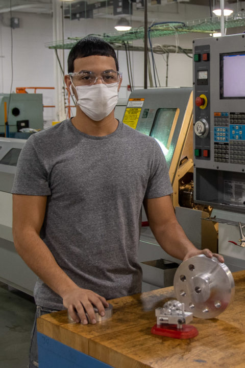
Angel D. Cruz, of Allentown
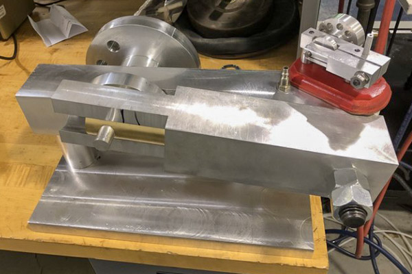
Cruz manufactured an aluminum compressed-air engine with a brass piston as a larger version of a project he completed in high school.
“I saw it as a personal project for myself,” he said. “I thought it would show my improvement in four years of college.”
He reverse engineered the high school version to increase the scale to about 18 inches by 8 inches by 8 inches. He machined the stand and flywheel using a Haas CNC mill and manually machined other parts.
“I had to redesign a lot to scale it up,” he said. His redesign also accommodated the raw materials available to him.
 “This is a good example of manufacturing processes demonstrating a 3D-modeled mechanism to CNC-machined parts to an actual working mechanism,” Good explained.
“With engineering, nothing ever works the first time you design it,” Cruz said of the challenges involved with the project. “You’re always going to have to make tweaks. It’s kind of the name of the game; you almost expect that to happen.”
How it works: Compressed air goes into an air nipple, pushes the brass piston, and the piston’s movement back and forth – as the chamber fills with and loses air – turns a flywheel.
Cruz, a graduate of William Allen High School in Allentown, chose the college’s manufacturing engineering technology major after completing machining courses during high school at Lehigh County Career & Technical Institute.
“My father is an electrician and has been in an industrial environment all his life,” Cruz explained. “Sometimes I went to work with him, and I saw the machines (like those in the college’s Automated Manufacturing Lab). I saw they had the program at the technical institute. I knew I wanted to get into engineering, and I thought this would be a good field.”

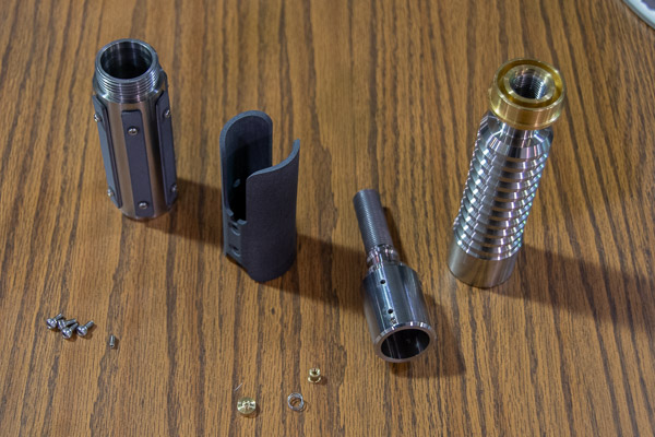
Ethan S. Rhodes-O’Brien, of Mechanicsburg
“I’ve been a ‘Star Wars’ fan since I was 5 or 6 years old and saw my first movie,” Rhodes-O’Brien said. “I wanted to build something that would set me apart. I wanted it to be high quality to reflect my machining skills.”
Goal met: Rhodes-O’Brien achieved impressive precision in the light saber, which Good said started with “incredible design.”
The saber contains more than two dozen parts, all fabricated by Rhodes-O’Brien. The hilt – or handle – was CNC machined to close tolerances on stainless steel, tool steel and brass.
Because the hilt’s two halves close around the “chassis” that holds all the light saber’s integrated electronics, the project required a great deal of internal threading and boring work.
“Stainless steel is one of the most challenging materials to work with,” Good explained.
 “I cannot estimate the time I spent on stainless steel machining,” Rhodes-O’Brien said. “I worked on it all semester.”
Most of it was lathe work, he said. He also did indexing on a mill to make fastener holes for the shroud that overlays the hilt.
Rhodes-O’Brien “laser sintered” the shroud, made up of eight nylon grips that attach to the hilt. The additive manufacturing process, he explained, uses a laser to fuse nylon powder, one microscopic layer at a time, to build a structure. Each layer is 3/1,000 of an inch in thickness, or about the diameter of one human hair. His total print time for three light saber shrouds was 46 hours.
Inside the hilt is a circuit board that tracks movement and emits sounds that react to that movement in real time – emitting the signature sound “Star Wars” fans hear in the movies. That includes, of course, blaster effects.
Rhodes-O’Brien took machining courses while a student at Northern High School in York County. After graduation, he worked as a CNC operator for a couple of years, then decided to further his education.
“I like the fact that you can make pretty much anything you can think of,” Rhodes-O’Brien said. “Any interest you have here, you can bring it to life in a really interesting way.”
“Pretty much every industry in the world is dependent in some way on manufacturing,” he added. “People making candy molds or making parts for rocket ships, they are all in the same field.”
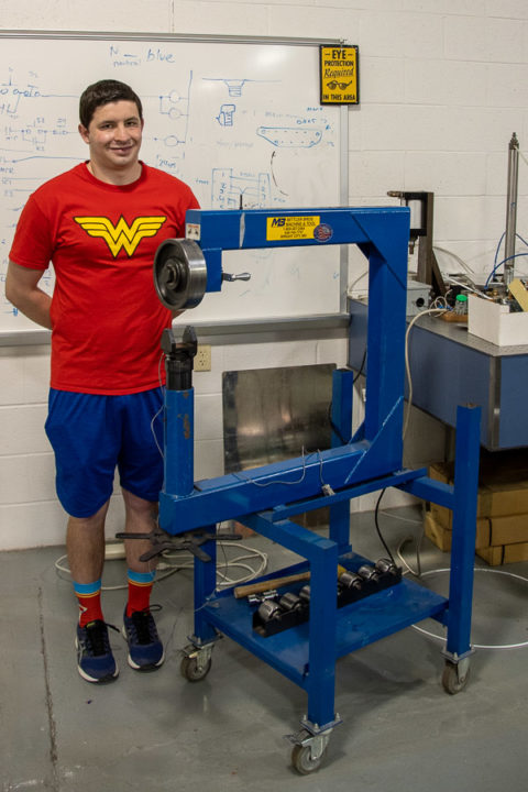
Daniel V. Gianelle, of Salisbury, Maryland
Gianelle’s project, the first of its kind, fulfills a request from the college’s automotive restoration major by adding a force sensor (also called a load cell or a force transducer) to measure tension, compression and pressure – to an English wheel roller.
English wheel rollers are used to shape sheet metal, such as fenders.
“Initially, the idea was to design and build an entire English wheel roller machine and integrate a force sensor to display the forces applied,” Good explained. “An entire wheel was designed by an engineering design student for a capstone project. The following year, the manufacturing department evaluated the project for manufacturability.”
When faculty determined that the cost of steel alone for the project was far more than the cost of a purchased machine, they decided to modify an existing English wheel roller.
To accomplish the work, Gianelle modified the wheel holder to install the load cell, wired it, and developed housing to show the sensor’s measurements.
Christopher M. Schweikert, of Jamison
Schweikert’s project was born in his second week of classes as a first-year Penn College student, when he made the three-hour trip home for the first time and, on the way, his engine lost all oil and locked up. Fortunately, his brother had a spare engine that he reconfigured to fit, and Schweikert was able to keep driving his truck. Meanwhile, the 1997 Cummins 12-valve turbo diesel engine is waiting for a rebuild – giving Schweikert the opportunity to add an innovative muiltifunctional intake manifold that could appeal to a variety of customers.
 “This project is four years in the making,” he said. “I never thought it would be my senior project.”
In fact, of the three projects he proposed to faculty last fall, this was his second choice; he thought it would be boring.
But nine revisions and a thousand SolidWorks files later, Schweikert is pleased.
“I haven’t found one that has these features and this design,” he said.
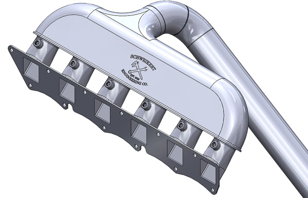
His primary goal in designing a custom intake manifold, which supplies the fuel/air mixture to the cylinders, was to increase the velocity of air flow compared to the stock version.
To achieve greater air flow, his design eliminates any 90-degree bends, which reduce the flow of air by half with each bend. Instead, the tubing that leads to the head follows an arc. But designing it to also fit around other engine components was a challenge.
“I knew people use these engines for a lot of things,” Schweikert said, so his design also allows the use of propane, water methanol or nitrous.
 With the option to safely inject other gases, the multifunctional intake manifold may appeal to customers with varying goals: Those seeking to increase their miles per gallon can inject propane, while those seeking higher horsepower can inject nitrous or water methanol – which keeps the engine cooler by reducing the temperature of the air in the intake.
The list of technologies he integrated into the project includes rapid prototyping, CNC machining, plasma cutting and wire electric discharge machining. Challenges included learning how to create runners (the tubing that channels intake air to the intake ports) that transition from round on one end to square on the other.
“It really is a project that encompasses everything I’ve learned here, whether from Baja or from classes. It’s really nice to be able to show that,” said Schweikert, a four-year member of the college’s Baja SAE team and president during his senior year.
And while he’s still waiting to rebuild his engine, Schweikert appreciates the outcome: “It was a blessing, in a way, because I ended up with a senior project I really care about, and I learned a lot, and I’m really proud of my design.”
Even so, he’s already planning version 2.0.

Isaac M. Johnson, of Williamsport
Johnson’s project creates a new product for bowfishing enthusiasts.
Bowfishing, Johnson explained, combines archery equipment and a fishing reel to shoot fish with a bow and arrow.
Being on the water carries the inherent risk of dropping a bow fishing rig – quickly putting an end to one’s fishing trip – “and strong animals, like stingrays and alligators, can pull the bow from your hand,” Johnson explained.
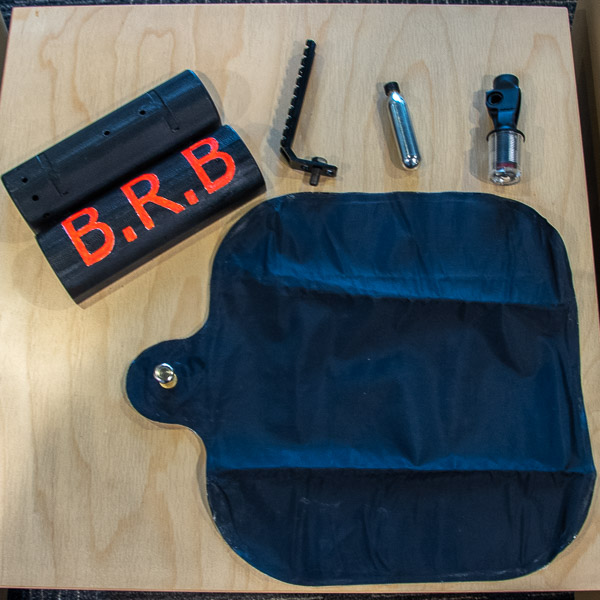 For that reason, he developed the Bow Retrieval Buoy, a self-inflating device that attaches to a bowfishing rig (and cleverly shares its initials with the common texting abbreviation for “be right back”).
Using an inflator mechanism similar to those made for self-inflating life jackets and pack rafts, he designed an air/gas bladder using nylon material that can be welded and sealed to itself. Archimedes’ principle of displacement (an object immersed in a fluid is buoyed by a force equal to the weight of the fluid displaced) and the ideal gas law (an equation, based on a hypothetical ideal gas, that expresses the relationship between pressure, volume, temperature and amount of a gas) were both part of his calculations.
With the bladder and method of inflation ready, he designed and 3D printed the BRB’s housing to hold the inflator, a carbon dioxide cartridge, and the air bladder and to allow mounting to the bow. The housing, printed of ABS plastic, features hinges to allow it to pop open when the device activates.
Johnson tested the BRB in Rose Valley Lake:
http://www.youtube.com/watch?v=5nDEdxJBdUg
“How many people do you know who can make – or specify how to manufacture – just about anything?” asked John M. Good, instructor of automation and computer integrated manufacturing, in introducing the projects prior to the students’ capstone presentations. “These nine manufacturing engineering technology students are uniquely skilled.”
The projects were initiated in the fall, during the Senior Seminar Lecture course, which teaches the theory and practice of defining, planning and cost-estimating engineering problems and includes a formal capstone project proposal. The projects, Good explained, evolved from students’ own ideas, were requested by someone or were simply a form of research and experimentation to determine whether something could be done.
This spring, during the Senior Seminar Lab, the students completed and delivered the projects, each working under a faculty mentor.
“In most cases, the projects are a complex mechanism demonstrating many disciplines,” Good added.
“At least four of these projects may qualify for patents, and at least two are already protected by patent pending status,” he said.
A few of the senior projects:

Angel D. Cruz, of Allentown
Compressed air engine
Cruz manufactured an aluminum compressed-air engine with a brass piston as a larger version of a project he completed in high school.
“I saw it as a personal project for myself,” he said. “I thought it would show my improvement in four years of college.”
He reverse engineered the high school version to increase the scale to about 18 inches by 8 inches by 8 inches. He machined the stand and flywheel using a Haas CNC mill and manually machined other parts.
“I had to redesign a lot to scale it up,” he said. His redesign also accommodated the raw materials available to him.
 “This is a good example of manufacturing processes demonstrating a 3D-modeled mechanism to CNC-machined parts to an actual working mechanism,” Good explained.
“With engineering, nothing ever works the first time you design it,” Cruz said of the challenges involved with the project. “You’re always going to have to make tweaks. It’s kind of the name of the game; you almost expect that to happen.”
How it works: Compressed air goes into an air nipple, pushes the brass piston, and the piston’s movement back and forth – as the chamber fills with and loses air – turns a flywheel.
Cruz, a graduate of William Allen High School in Allentown, chose the college’s manufacturing engineering technology major after completing machining courses during high school at Lehigh County Career & Technical Institute.
“My father is an electrician and has been in an industrial environment all his life,” Cruz explained. “Sometimes I went to work with him, and I saw the machines (like those in the college’s Automated Manufacturing Lab). I saw they had the program at the technical institute. I knew I wanted to get into engineering, and I thought this would be a good field.”

Ethan S. Rhodes-O’Brien, of Mechanicsburg
Light saber
“I’ve been a ‘Star Wars’ fan since I was 5 or 6 years old and saw my first movie,” Rhodes-O’Brien said. “I wanted to build something that would set me apart. I wanted it to be high quality to reflect my machining skills.”
Goal met: Rhodes-O’Brien achieved impressive precision in the light saber, which Good said started with “incredible design.”
The saber contains more than two dozen parts, all fabricated by Rhodes-O’Brien. The hilt – or handle – was CNC machined to close tolerances on stainless steel, tool steel and brass.
Because the hilt’s two halves close around the “chassis” that holds all the light saber’s integrated electronics, the project required a great deal of internal threading and boring work.
“Stainless steel is one of the most challenging materials to work with,” Good explained.
 “I cannot estimate the time I spent on stainless steel machining,” Rhodes-O’Brien said. “I worked on it all semester.”
Most of it was lathe work, he said. He also did indexing on a mill to make fastener holes for the shroud that overlays the hilt.
Rhodes-O’Brien “laser sintered” the shroud, made up of eight nylon grips that attach to the hilt. The additive manufacturing process, he explained, uses a laser to fuse nylon powder, one microscopic layer at a time, to build a structure. Each layer is 3/1,000 of an inch in thickness, or about the diameter of one human hair. His total print time for three light saber shrouds was 46 hours.
Inside the hilt is a circuit board that tracks movement and emits sounds that react to that movement in real time – emitting the signature sound “Star Wars” fans hear in the movies. That includes, of course, blaster effects.
Rhodes-O’Brien took machining courses while a student at Northern High School in York County. After graduation, he worked as a CNC operator for a couple of years, then decided to further his education.
“I like the fact that you can make pretty much anything you can think of,” Rhodes-O’Brien said. “Any interest you have here, you can bring it to life in a really interesting way.”
“Pretty much every industry in the world is dependent in some way on manufacturing,” he added. “People making candy molds or making parts for rocket ships, they are all in the same field.”

Daniel V. Gianelle, of Salisbury, Maryland
English wheel roller with pressure sensor
Gianelle’s project, the first of its kind, fulfills a request from the college’s automotive restoration major by adding a force sensor (also called a load cell or a force transducer) to measure tension, compression and pressure – to an English wheel roller.
English wheel rollers are used to shape sheet metal, such as fenders.
“Initially, the idea was to design and build an entire English wheel roller machine and integrate a force sensor to display the forces applied,” Good explained. “An entire wheel was designed by an engineering design student for a capstone project. The following year, the manufacturing department evaluated the project for manufacturability.”
When faculty determined that the cost of steel alone for the project was far more than the cost of a purchased machine, they decided to modify an existing English wheel roller.
To accomplish the work, Gianelle modified the wheel holder to install the load cell, wired it, and developed housing to show the sensor’s measurements.
Christopher M. Schweikert, of Jamison
Multifunctional intake manifold
Schweikert’s project was born in his second week of classes as a first-year Penn College student, when he made the three-hour trip home for the first time and, on the way, his engine lost all oil and locked up. Fortunately, his brother had a spare engine that he reconfigured to fit, and Schweikert was able to keep driving his truck. Meanwhile, the 1997 Cummins 12-valve turbo diesel engine is waiting for a rebuild – giving Schweikert the opportunity to add an innovative muiltifunctional intake manifold that could appeal to a variety of customers.
 “This project is four years in the making,” he said. “I never thought it would be my senior project.”
In fact, of the three projects he proposed to faculty last fall, this was his second choice; he thought it would be boring.
But nine revisions and a thousand SolidWorks files later, Schweikert is pleased.
“I haven’t found one that has these features and this design,” he said.
His primary goal in designing a custom intake manifold, which supplies the fuel/air mixture to the cylinders, was to increase the velocity of air flow compared to the stock version.
To achieve greater air flow, his design eliminates any 90-degree bends, which reduce the flow of air by half with each bend. Instead, the tubing that leads to the head follows an arc. But designing it to also fit around other engine components was a challenge.
“I knew people use these engines for a lot of things,” Schweikert said, so his design also allows the use of propane, water methanol or nitrous.
 With the option to safely inject other gases, the multifunctional intake manifold may appeal to customers with varying goals: Those seeking to increase their miles per gallon can inject propane, while those seeking higher horsepower can inject nitrous or water methanol – which keeps the engine cooler by reducing the temperature of the air in the intake.
The list of technologies he integrated into the project includes rapid prototyping, CNC machining, plasma cutting and wire electric discharge machining. Challenges included learning how to create runners (the tubing that channels intake air to the intake ports) that transition from round on one end to square on the other.
“It really is a project that encompasses everything I’ve learned here, whether from Baja or from classes. It’s really nice to be able to show that,” said Schweikert, a four-year member of the college’s Baja SAE team and president during his senior year.
And while he’s still waiting to rebuild his engine, Schweikert appreciates the outcome: “It was a blessing, in a way, because I ended up with a senior project I really care about, and I learned a lot, and I’m really proud of my design.”
Even so, he’s already planning version 2.0.

Isaac M. Johnson, of Williamsport
Bow retrieval buoy
Johnson’s project creates a new product for bowfishing enthusiasts.
Bowfishing, Johnson explained, combines archery equipment and a fishing reel to shoot fish with a bow and arrow.
Being on the water carries the inherent risk of dropping a bow fishing rig – quickly putting an end to one’s fishing trip – “and strong animals, like stingrays and alligators, can pull the bow from your hand,” Johnson explained.
 For that reason, he developed the Bow Retrieval Buoy, a self-inflating device that attaches to a bowfishing rig (and cleverly shares its initials with the common texting abbreviation for “be right back”).
Using an inflator mechanism similar to those made for self-inflating life jackets and pack rafts, he designed an air/gas bladder using nylon material that can be welded and sealed to itself. Archimedes’ principle of displacement (an object immersed in a fluid is buoyed by a force equal to the weight of the fluid displaced) and the ideal gas law (an equation, based on a hypothetical ideal gas, that expresses the relationship between pressure, volume, temperature and amount of a gas) were both part of his calculations.
With the bladder and method of inflation ready, he designed and 3D printed the BRB’s housing to hold the inflator, a carbon dioxide cartridge, and the air bladder and to allow mounting to the bow. The housing, printed of ABS plastic, features hinges to allow it to pop open when the device activates.
Johnson tested the BRB in Rose Valley Lake:
http://www.youtube.com/watch?v=5nDEdxJBdUg